Need accurate pipe dimensions for your next project? Our comprehensive pipe dimensions chart provides instant access to nominal pipe sizes, wall thickness specifications, and weight calculations for carbon and stainless steel pipes from 1/8” to 48“.
What is a Pipe Dimensions Chart?
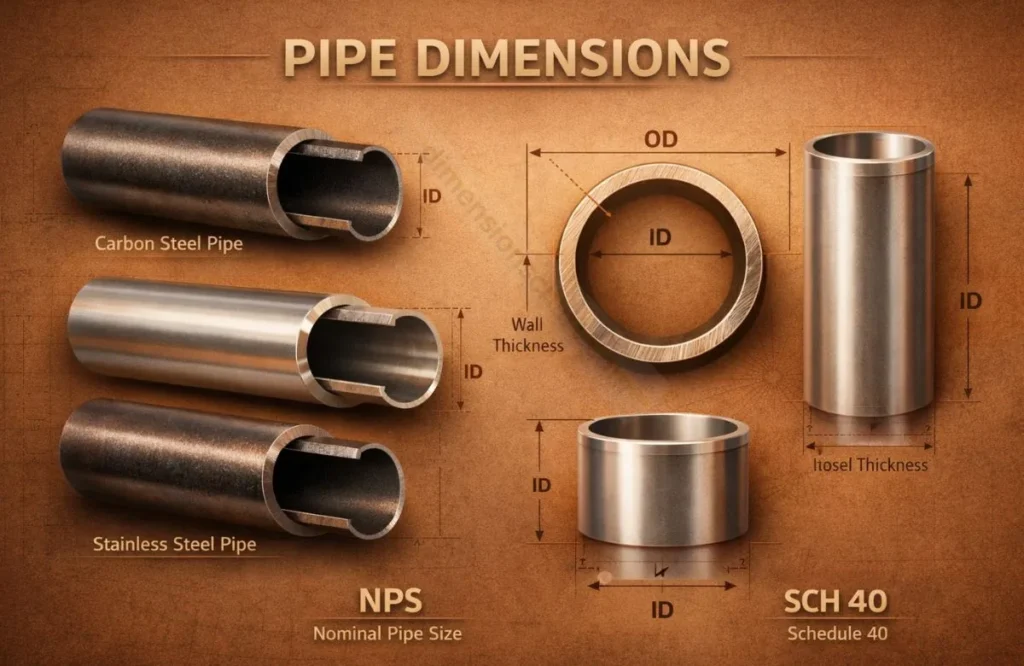
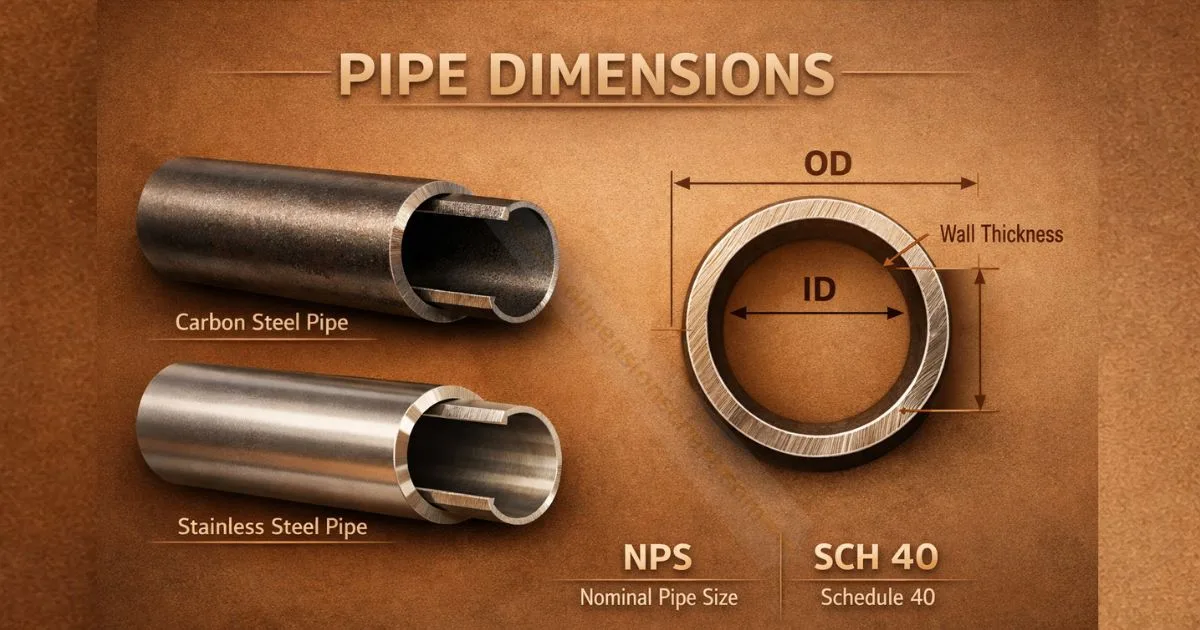
A pipe dimensions chart is a technical reference tool that displays critical specifications for industrial piping systems. It provides engineers, plumbers, and fabricators with standardized measurements including Outside Diameter (OD), Inside Diameter (ID), wall thickness, and weight per foot.
These charts follow ANSI/ASME B36.10M standards for carbon steel pipes and ANSI/ASME B36.19M for stainless steel applications. According to the American Society of Mechanical Engineers, standardized pipe dimensions ensure compatibility across global manufacturing and installation processes.
Standard Pipe Dimensions Chart – NPS 1/8″ to 48″
| Nominal Pipe Size (NPS) | Outside Diameter (OD) | Schedule | Wall Thickness | Inside Diameter (ID) | Weight (lbs/ft) |
|---|---|---|---|---|---|
| 1/8″ | 0.405″ | 40, STD | 0.068″ | 0.269″ | 0.24 |
| 1/4″ | 0.540″ | 40, STD | 0.088″ | 0.364″ | 0.42 |
| 3/8″ | 0.675″ | 40, STD | 0.091″ | 0.493″ | 0.57 |
| 1/2″ | 0.840″ | 40, STD | 0.109″ | 0.622″ | 0.85 |
| 3/4″ | 1.050″ | 40, STD | 0.113″ | 0.824″ | 1.13 |
| 1″ | 1.315″ | 40, STD | 0.133″ | 1.049″ | 1.68 |
| 1-1/4″ | 1.660″ | 40, STD | 0.140″ | 1.380″ | 2.27 |
| 1-1/2″ | 1.900″ | 40, STD | 0.145″ | 1.610″ | 2.72 |
| 2″ | 2.375″ | 40, STD | 0.154″ | 2.067″ | 3.65 |
| 2-1/2″ | 2.875″ | 40, STD | 0.203″ | 2.469″ | 5.79 |
| 3″ | 3.500″ | 40, STD | 0.216″ | 3.068″ | 7.58 |
| 4″ | 4.500″ | 40, STD | 0.237″ | 4.026″ | 10.79 |
| 6″ | 6.625″ | 40, STD | 0.280″ | 6.065″ | 18.97 |
| 8″ | 8.625″ | 40, STD | 0.322″ | 7.981″ | 28.55 |
| 10″ | 10.750″ | 40, STD | 0.365″ | 10.020″ | 40.48 |
| 12″ | 12.750″ | 40, STD | 0.375″ | 12.000″ | 49.56 |
The chart above displays standard Schedule 40 pipes, the most commonly used in industrial applications. For Schedule 80, Schedule 160, or extra strong (XS) specifications, refer to our downloadable comprehensive chart featuring all schedule variations.
How to Read a Pipe Dimensions Chart
Understanding Nominal Pipe Size (NPS) is critical when selecting pipes. The NPS represents the approximate bore diameter, not the actual outside diameter. For example, a 2” NPS pipe has an actual OD of 2.375″ and an ID that varies based on wall thickness.
Pipe schedules determine wall thickness and pressure ratings. A Schedule 40 pipe has thinner walls than Schedule 80, which handles higher pressure applications. The Steel Tube Institute confirms that schedule numbers indicate the pipe’s pressure-bearing capacity, calculated using Barlow’s formula.
Key specifications to reference include OD (remains constant), ID (changes with schedule), wall thickness (increases with schedule number), and weight per foot (used for structural load calculations and material costs).
Pipe Schedule Numbers Explained
Pipe schedule is a standardized system that defines wall thickness relative to pipe diameter. Common schedules include Schedule 10, 20, 40, 80, 120, and 160, with higher numbers indicating thicker walls and greater pressure capacity.
Schedule 40 is the industry standard for general-purpose applications with moderate pressure requirements. Schedule 80 provides 50% thicker walls for high-pressure systems, chemical processing plants, and steam lines. According to ASME standards, Schedule 160 handles extreme pressure environments exceeding 3,000 PSI.
Carbon Steel vs Stainless Steel Pipe Dimensions
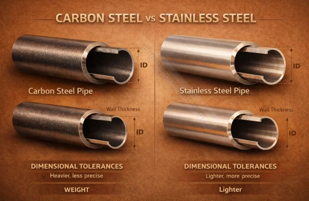
Carbon steel pipes follow ANSI B36.10M specifications and are used in 80% of industrial applications due to cost-effectiveness. Stainless steel pipes follow ANSI B36.19M standards and provide corrosion resistance for food processing, pharmaceutical, and marine environments.
Dimensional differences exist between materials. While OD remains standardized, stainless steel pipes typically have slightly different wall thickness tolerances. Weight calculations vary significantly—stainless steel weighs approximately 2-8% more than carbon steel for identical dimensions due to higher density (0.289 lb/in³ vs 0.284 lb/in³).
Conclusion
This pipe dimensions chart provides the essential specifications professionals need for accurate project planning and material selection. Reference these standardized measurements to ensure compatibility, safety, and code compliance across all piping applications.
Request a quote for custom pipe cutting, threading, or beveling services tailored to your exact dimensional requirements.
FAQ’s
What is the difference between pipe schedule and pipe dimensions?
Pipe schedule refers specifically to the wall thickness designation, while pipe dimensions encompass all measurements including outside diameter, inside diameter, schedule rating, and weight per foot. Schedule numbers like 40 or 80 indicate how thick the pipe walls are, which directly affects the pipe’s ability to handle pressure.
How do I determine the right pipe size for my project?
Select pipe size based on three factors: required flow rate (measured in GPM), operating pressure (PSI rating), and application type. Use the pipe dimensions chart to match your pressure requirements with the appropriate schedule. For pressures below 300 PSI, Schedule 40 suffices. Above 600 PSI requires Schedule 80 or higher.
Are pipe dimensions the same worldwide?
ANSI/ASME standards dominate in the United States, while DN (Diameter Nominal) is used in Europe following ISO 6708 standards. Japanese JIS and British BSI standards also exist. However, most international projects reference ANSI specifications for compatibility, making US pipe dimension charts globally applicable for cross-border projects.
What does NPS mean on a pipe dimensions chart?
NPS (Nominal Pipe Size) represents the approximate inside diameter designation, not the actual measured dimension. This standardized naming convention allows professionals to reference pipe sizes universally. For instance, a 2“ NPS pipe actually has a 2.375” outside diameter and varying inside diameters depending on schedule.
How is pipe weight calculated?
Pipe weight is calculated using the formula: Weight = (OD – Wall Thickness) × Wall Thickness × 10.68 for steel. This accounts for the material density and dimensional specifications. Most pipe dimension charts provide pre-calculated weights per linear foot, eliminating manual calculations for project planning and material cost estimation.

Burhan Ali is the founder and author of DimensionsChart.com, providing accurate size charts, measurements, and guides for smarter buying decisions.